Harness the Power of Radio Waves for a Better Tomorrow
An RF and Microwave laboratory is the facility where students in Electrical and Electronic Engineering department can learn about the design, analysis, and measurement of RF and microwave circuits and devices. The laboratory contains a variety of equipment, such as signal generators, spectrum analyzers, network analyzers, and microwave test fixtures, etc.
The RF and Microwave laboratory is an essential part of the curriculum for DEEE students. It provides students with the hands-on experience they need to understand the principles of RF and microwave engineering and to apply those principles to real-world problems. Some of the experiments that are performed in this lab are measuring the frequency and amplitude of an RF signal, determining the impedance of a transmission line, analyzing the scattering parameters of a microwave device, designing and testing an RF amplifier, characterizing the radiation pattern of an antenna, etc. The RF and Microwave laboratory is a valuable resource for our students and it provides them with the knowledge and skills they need to succeed in this challenging and rewarding field.
EQUIPMENT AND EXPERIMENTAL SETUPS
Below, you will find pictures of laboratory setups, equipment, etc., belonging to the RF and Microwave laboratory.
| DESIGN TOOLS | |||
|
AWR Design Environment |
Ansoft HFSS/Designer |
||
|
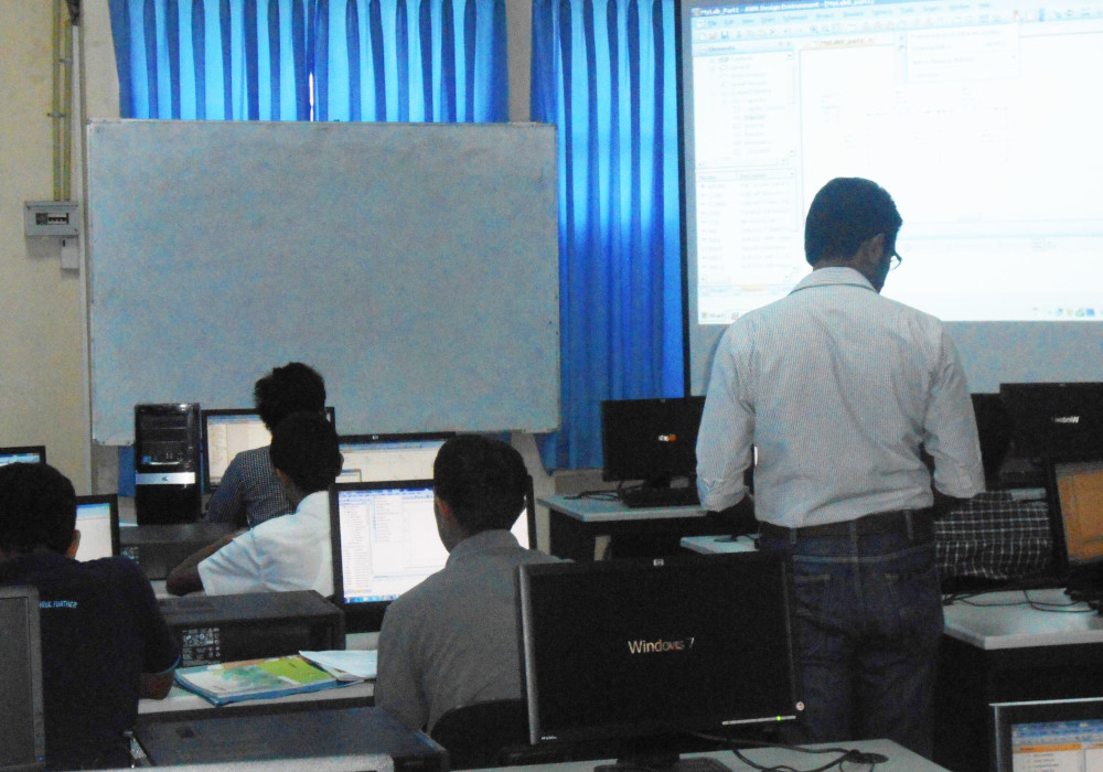
Both UG and PG teaching is conducted using AWRDE V11 Design. In addition to laboratory and class room use, the license server provides home access to registered students for completing their laboratory classes off working hours. Forty users can simultaneously access the software. | 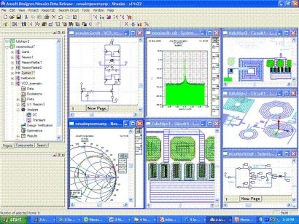
|
In addition to AWR Design Environment, the laboratory also uses Ansoft HFSS and Designer mainly for research and project work. |
| MEASUREMENT FACILITIES | |||
| Microwave Network Analyzer | RF Network Analyzer | ||
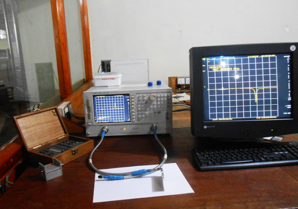 |
The laboratory is equipped with an Agilent 8719ES vector network analyzer for measurements up to 13.5 GHz. Shown in the figure is the Agilent Network analyzer interfaced to a PC for automated measurement. A test fixture and a 3.5mm calibration kit can also be seen in the picture. |
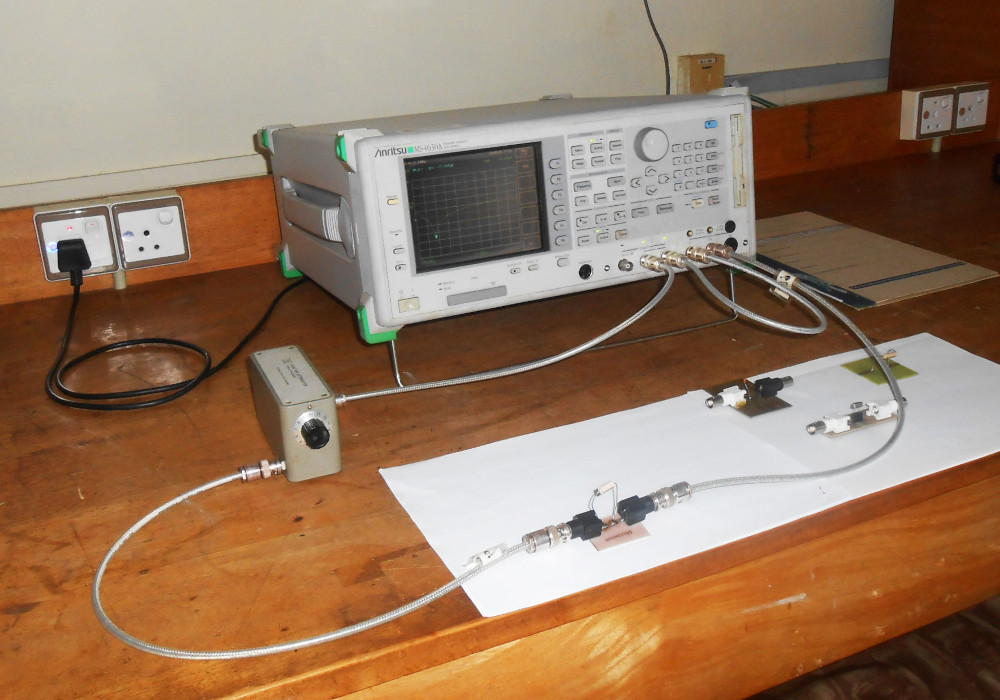 |
The RF and microwave measurements are also supplemented by Anritsu RF Network Analyzer. |
| Spectrum Analyzers | Noise Figure Meter | ||
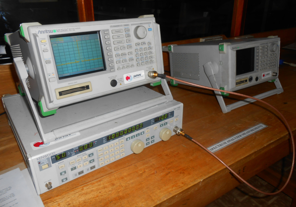 |
The RF microwave measurements are also supplemented by two Anritsu Spectrum Analyzers. The picture above shows a R.F. synthesized source connected to a spectrum analyzer in a CNR measurement experiment.
|
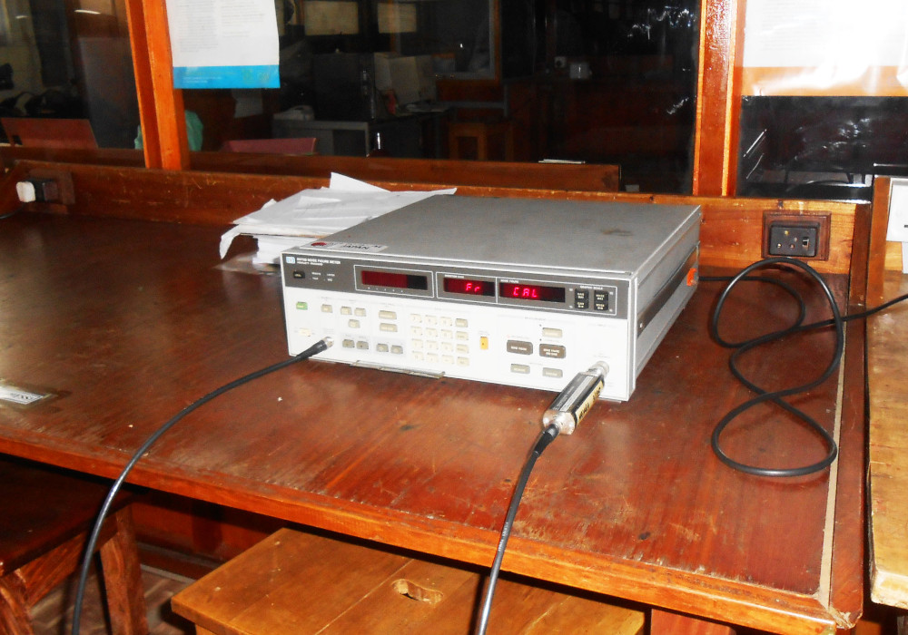 |
Shown in the picture is the calibrated noise source connected to the noise figure meter to calibrate the instrument. |
| FABRICATION FACILITIES | |||
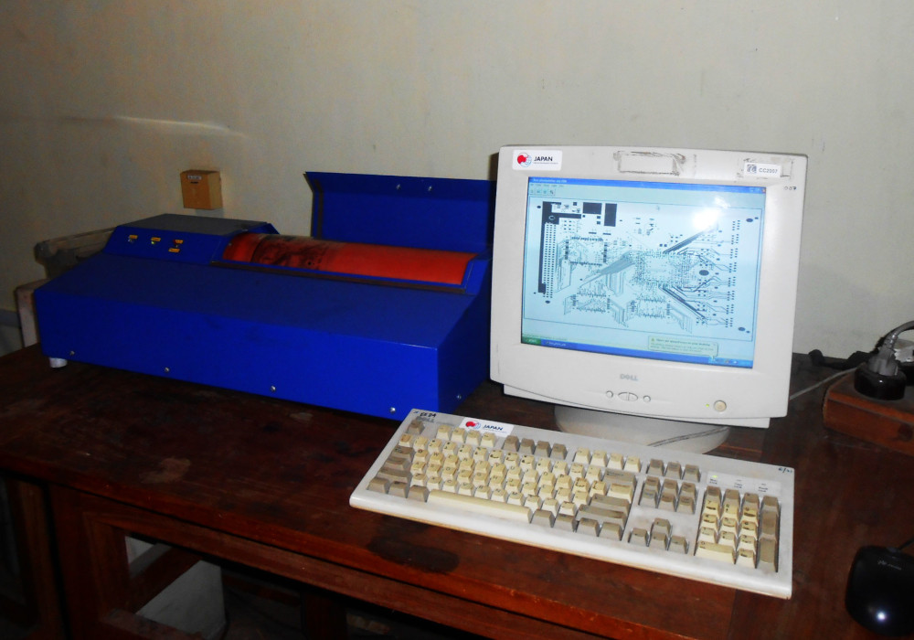
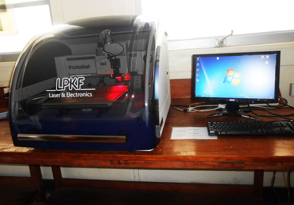
| Microwave and Rf circuits are fabricated in-house using the facilities of the PCB Fabrication laboratory of the department. The equipment in the PCB laboratory has been carefully selected to meet the high accuracies demanded by microwave applications. These include the LPKF-S63 PCB milling machine with a 100 micron accuracy and the Photoplotter with a 50 micron accuracy. | |||
| Photoplotter | LPKF S-63 CNC Milling Machine | ||
|
|
||
| FABRICATED CIRCUIT SAMPLES | |||
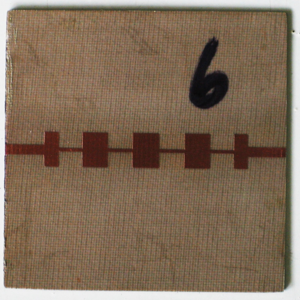
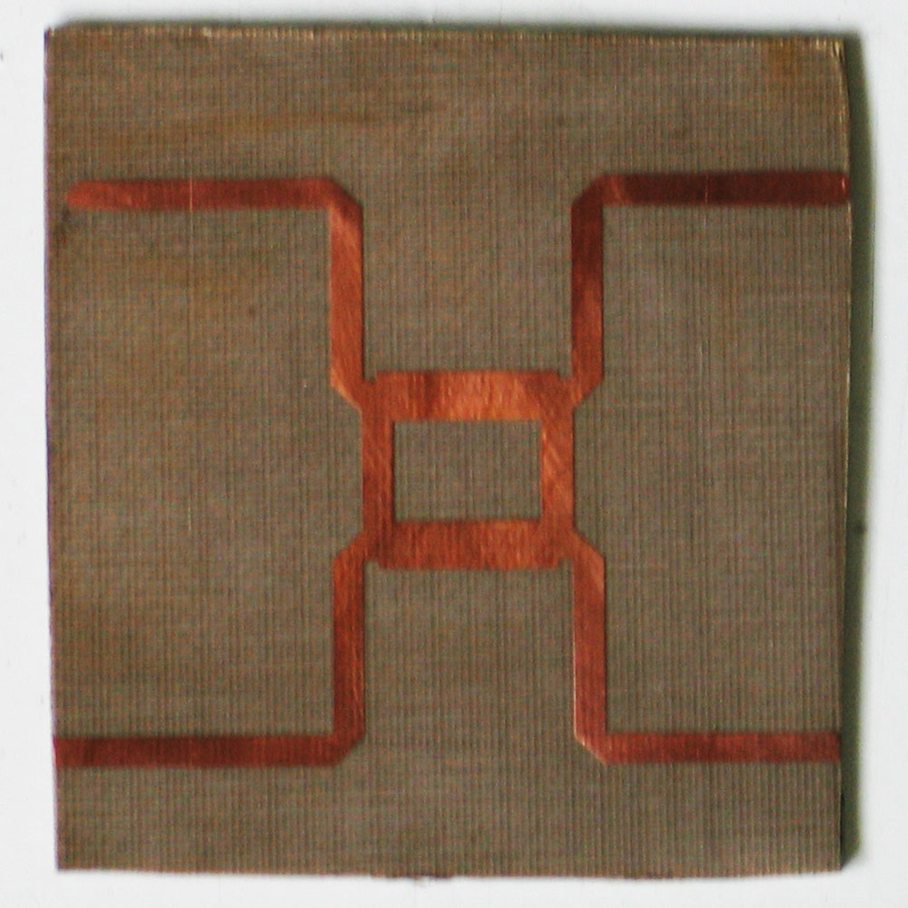
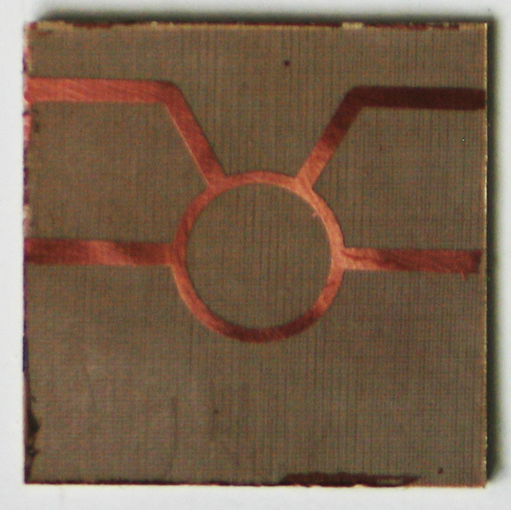
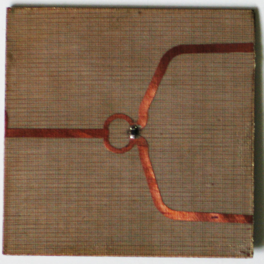
| Shown below are a collection of circuits fabricated as part of the EE554 Microwave Techniques course. This is an undergraduate course of 3 credits with a 30 hour laboratory component. All the following circuits are designed for a center frequency of 5 GHz. | |||
| Low Pass Filter | Branch Line Coupler | Rat-race Coupler | Wilkinson's Power Divider |
 |
 |
 |
 |

